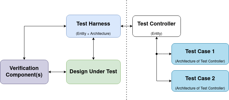
VHDL Design Patterns: Test Controller
Chapter 5 of OSVVM’s Test Writer’s User Guide explains how their testbench framework consists of a test sequencer, TestCtrl, and a top level testbench which they call a test harness. However, no examples are given on how to create this setup. I resorted to digging around in OSVVM’s own testbenches to find out how to do that. This post will cover how to create your own setup of the testbench framework with a test controller.
Table of Contents
This setup is entirely overkill for simple designs, but perhaps appropriate for board- or system-level testbenches i.e. testbenches going beyond the Affirm/Check/Asserts of self checking testbenches but rather testbenches that can get up to tens of thousands of lines and are checking the integration of several components for example.
The architecture of testbenches tends towards something like the following image:
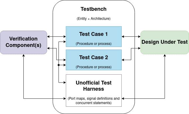
With OSVVM’s approach of using a Test Controller to separate the test harness and the test cases we get a clear interface to the design under test (DUT).
Template
I based this template on the tests in OSVVM’s UART verification component. To use the template, clone this repository and follow the instructions in the readme. You can see a usage example at the end of this post.
Test Controller
We’ll start with the test control entity which provides a configuration point later on for hooking in you test cases.
1
2
3
4
5
6
7
8
9
10
11
12
13
14
15
16
17
18
19
20
21
22
--! \file test_controller.vhd

library ieee;
  use ieee.std_logic_1164.all;

library OSVVM;
  context OSVVM.OsvvmContext;


--! \brief Test Controller for 'example'.
entity test_controller is
  generic(
    -- Template: Generics that you want to be able to configure.
  );
  port(
    -- Template: DUT Interface Signals, i.e. the ports you want to use to access your design under test.
    --           Set them all to inout mode.
    --           s: inout std_logic

    -- Template: Global Signals, i.e. signals like clock or reset.
  );
end entity test_controller;
Test Harness
The test harness serves the purpose of connecting the design under test to the test controller. This leads to a reusable setup which is useful for large designs with complicated setups, like board-level simulations.
1
2
3
4
5
6
7
8
9
10
11
12
13
14
15
16
17
18
19
20
21
22
23
24
25
26
27
28
29
30
31
32
33
34
35
36
37
38
39
40
41
42
43
44
45
46
47
48
49
50
51
52
53
54
55
56
57
--! \file test_harness.vhd

library ieee;
  use ieee.std_logic_1164.all;

library OSVVM;
  context OSVVM.OsvvmContext;

--! \brief Test harness for 'example'.
entity example_tb is
  generic(
    -- Template: Generics.
  );
end entity example_tb;

--! \brief Connect the test_controller to the DUT.
architecture test_harness of example_tb is

  -- Template: Define the Global Signals.

  --! \brief Stimulus generation and synchronization
  component test_controller is
    generic(
      -- Template: Generics.
    );
    port(
      -- Template: DUT Interface Signals.
      --           s: inout std_logic

      -- Template: Global Signals.
    );
  end component test_controller;

  -- Template: Define the DUT Interface Signals.
  --           signal s: std_logic;

begin
  -- Template: Generate any global signals,
  --           e.g. OSVVM's CreateClock and CreateReset.

  -- Template: Hook up your design under test to the test_controller component.
  dut: entity work.example
    port map(
      -- Template: s => s
    );

  test_controller_1: component test_controller
    generic map(
      -- Template: Generics.
    )
    port map(
      -- Template: DUT Interface Signals.
      --           s => s

      -- Template: Global Signals.
    );
end architecture test_harness;
Test Case
In the test case you finally implement your test code. As you can see in the listing below I have numbered the file, this is an indication that we can create multiple test cases and reuse the harness and controller.
1
2
3
4
5
6
7
8
9
10
11
12
13
14
15
16
17
18
19
20
21
22
23
24
25
26
27
28
29
30
31
32
33
34
35
36
37
38
39
40
41
42
43
44
45
46
47
48
49
50
51
52
53
54
55
56
57
58
--! \file test_case_1.vhd

--! \brief Test that thing we need to test.
--! \test First test of many.
architecture test_case_1 of test_controller is
  signal test_done : integer_barrier := 1;
  signal setup_done : integer_barrier := 1;
begin

  --! \brief Set up logging and wait for end of test.
  control_process: process is
    constant TIMEOUT: time := 10 ms;
  begin
    -- Init logs.
    SetAlertLogName("example_tb_test_case_1");

    -- Wait for testbench init.
    wait for 0 ns;  wait for 0 ns;

    -- Template: Wait for design to init, e.g. wait until reset = '0'.

    WaitForBarrier(setup_done);

    -- Wait for test to finish.
    WaitForBarrier(test_done, TIMEOUT);
    AlertIf(now >= TIMEOUT, "Test finished due to timeout");
    AlertIf(GetAffirmCount < 1, "Test is not Self-Checking");

    ReportAlerts;
  end process control_process;

  --! \brief Executes tests.
  check_process: process is
    -- Template: Variables...
  begin
    WaitForBarrier(setup_done);
    -- Template: Interact with your design under test and check results.
    --           i.e. OSVVM's AffirmIf and friends.
    --           s <= '0';
    --           wait for 1 ns;
    --           AffirmIf(s = '0', "simplest example");

    WaitForBarrier(test_done);
    wait;
  end process check_process;
end architecture test_case_1;

--! \brief Configure testbench.
--! \details We set the architecture of the test_controller component in
--!          the test_harness to be test_case_1 which we defined
--!          in this file.
configuration example_tb_test_case_1 of example_tb is
  for test_harness
    for test_controller_1 : test_controller
      use entity work.test_controller(test_case_1);
    end for;
  end for;
end configuration example_tb_test_case_1;
Example
Let’s have a go at filling in the template for a half adder design from nandland which I used in previous posts. To reiterate my point from above, this is a complete overkill for such a simple design.
1
2
3
4
5
6
7
8
9
10
11
12
13
14
15
16
17
18
19
20
21
--! \file half_adder.vhd

library ieee;
use ieee.std_logic_1164.all;
use ieee.numeric_std.all;

entity half_adder is
  port (
    i_bit1  : in std_logic;
    i_bit2  : in std_logic;
    --
    o_sum   : out std_logic := '0';
    o_carry : out std_logic := '0'
    );
end half_adder;

architecture rtl of half_adder is
begin
  o_sum   <= i_bit1 xor i_bit2;
  o_carry <= i_bit1 and i_bit2;
end rtl;
The filled-in template follows, I’ve kept most of the template comments to highlight what changes I made when instantiating the template.
Test Controller
I’ve basically copied the port definition from the design, but set the port mode to inout on all ports.
1
2
3
4
5
6
7
8
9
10
11
12
13
14
15
16
17
18
19
20
21
22
23
24
25
26
27
--! \file test_controller.vhd

library ieee;
  use ieee.std_logic_1164.all;

library OSVVM;
  context OSVVM.OsvvmContext;


--! \brief Test Controller for 'half_adder'.
entity test_controller is
  generic(
    -- Template: Generics that you want to be able to configure.
    fail: boolean
  );
  port(
    -- Template: DUT Interface Signals, i.e. the ports you want to use to access your design under test.
    --           Set them to inout mode.
    bit1: inout std_logic;
    bit2: inout std_logic;

    sum: inout std_logic;
    carry: inout std_logic

    -- Template: Global Signals, i.e. signals like clock or reset.
  );
end entity test_controller;
Test Harness
For the test harness you copy the test_controller entity port definitions into the test_controller component, define the signals needed for the ports and finally connect the ports of the test_controller to your design.
1
2
3
4
5
6
7
8
9
10
11
12
13
14
15
16
17
18
19
20
21
22
23
24
25
26
27
28
29
30
31
32
33
34
35
36
37
38
39
40
41
42
43
44
45
46
47
48
49
50
51
52
53
54
55
56
57
58
59
60
61
62
63
64
65
66
67
68
69
70
71
72
--! \file test_harness.vhd

library ieee;
  use ieee.std_logic_1164.all;

library OSVVM;
  context OSVVM.OsvvmContext;

--! \brief Test harness for 'half_adder'.
entity half_adder_tb is
  generic(
    fail: boolean := true
  );
end entity half_adder_tb;

--! \brief Connect the test_controller to the DUT.
architecture test_harness of half_adder_tb is

  -- Template: Define the Global Signals.

  --! \brief Stimulus generation and synchronization
  component test_controller is
    generic(
      -- Template: Generics.
      fail: boolean
    );
    port(
      -- Template: DUT Interface Signals.
      bit1: inout std_logic;
      bit2: inout std_logic;

      sum: inout std_logic;
      carry: inout std_logic

      -- Template: Global Signals.
    );
  end component test_controller;

  -- Template: Define the DUT Interface Signals.
  signal bit1: std_logic;
  signal bit2: std_logic;
  signal sum: std_logic;
  signal carry: std_logic;

begin
  -- Template: Generate any global signals,
  --           e.g. OSVVM's CreateClock and CreateReset.

  -- Template: Hook up your design under test to the test_controller component.
  dut: entity work.half_adder
    port map(
      i_bit1 => bit1,
      i_bit2 => bit2,
      o_sum => sum,
      o_carry => carry
    );

  test_controller_1: component test_controller
    generic map(
      -- Template: Generics.
      fail => fail
    )
    port map(
      -- Template: DUT Interface Signals.
      bit1 => bit1,
      bit2 => bit2,
      sum => sum,
      carry => carry

      -- Template: Global Signals.
    );
end architecture test_harness;
Test Cases
The test case file is where the manual labor stops and you need to start thinking about how to test your design. I’ve really only added the stimulation and checks in the check_process here.
1
2
3
4
5
6
7
8
9
10
11
12
13
14
15
16
17
18
19
20
21
22
23
24
25
26
27
28
29
30
31
32
33
34
35
36
37
38
39
40
41
42
43
44
45
46
47
48
49
50
51
52
53
54
55
56
57
58
59
60
61
62
63
64
65
--! \file test_case_1.vhd

--! \brief Test that thing we need to test.
--! \test First test of many.
architecture test_case_1 of test_controller is
  signal test_done : integer_barrier := 1;
  signal setup_done : integer_barrier := 1;
begin

  --! \brief Set up logging and wait for end of test.
  control_process: process is
    constant TIMEOUT: time := 10 ms;
  begin
    -- Init logs.
    SetAlertLogName("half_adder_tb_test_case_1");

    -- Wait for testbench init.
    wait for 0 ns;

    -- Template: Wait for design to init, e.g. wait until reset = '0'.
    WaitForBarrier(setup_done);

    -- Wait for test to finish.
    WaitForBarrier(test_done, TIMEOUT);
    AlertIf(now >= TIMEOUT, "Test finished due to timeout");
    AlertIf(GetAffirmCount < 1, "Test is not Self-Checking");

    ReportAlerts;
  end process control_process;

  --! \brief Executes tests.
  check_process: process is
    -- Template: Variables...
  begin
    WaitForBarrier(setup_done);
    -- Template: Interact with your design under test and check results.
    --           i.e. OSVVM's AffirmIf and friends.
    bit1 <= '0';
    bit2 <= '0';
    wait for 1 ns; -- Allow signals to propagate
    AffirmIf(sum = '0', "Sum should be zero, was " & std_logic'image(sum));
    AffirmIf(carry = '0', "Carry should be zero, was " & std_logic'image(carry));

    bit1 <= '1';
    bit2 <= '0';
    wait for 1 ns; -- Allow signals to propagate
    AffirmIf(sum = '1', "Sum should be one, was " & std_logic'image(sum));
    AffirmIf(carry = '0', "Carry should be zero, was " & std_logic'image(carry));

    WaitForBarrier(test_done);
    wait;
  end process check_process;
end architecture test_case_1;

--! \brief Configure testbench.
--! \details We set the architecture of the test_controller component in
--!          the test_harness to be test_case_1 which we defined
--!          in this file.
configuration half_adder_tb_test_case_1 of half_adder_tb is
  for test_harness
    for test_controller_1 : test_controller
      use entity work.test_controller(test_case_1);
    end for;
  end for;
end configuration half_adder_tb_test_case_1;
1
2
3
4
5
6
7
8
9
10
11
12
13
14
15
16
17
18
19
20
21
22
23
24
25
26
27
28
29
30
31
32
33
34
35
36
37
38
39
40
41
42
43
44
45
46
47
48
49
50
51
52
53
54
55
56
57
58
59
60
61
62
63
64
65
66
67
68
69
70
--! \file test_case_2.vhd

--! \brief Test that thing we need to test.
--! \test First test of many.
architecture test_case_2 of test_controller is
  signal test_done : integer_barrier := 1;
  signal setup_done : integer_barrier := 1;
begin

  --! \brief Set up logging and wait for end of test.
  control_process: process is
    constant TIMEOUT: time := 10 ms;
  begin
    -- Init logs.
    SetAlertLogName("half_adder_tb_test_case_2");

    -- Wait for testbench init.
    wait for 0 ns;

    -- Template: Wait for design to init, e.g. wait until reset = '0'.
    WaitForBarrier(setup_done);

    -- Wait for test to finish.
    WaitForBarrier(test_done, TIMEOUT);
    AlertIf(now >= TIMEOUT, "Test finished due to timeout");
    AlertIf(GetAffirmCount < 1, "Test is not Self-Checking");

    ReportAlerts;
  end process control_process;

  --! \brief Executes tests.
  check_process: process is
    -- Template: Variables...
  begin
    WaitForBarrier(setup_done);
    -- Template: Interact with your design under test and check results.
    --           i.e. OSVVM's AffirmIf and friends.

    bit1 <= '0';
    bit2 <= '1';
    wait for 1 ns; -- Allow signals to propagate
    AffirmIf(sum = '1', "Sum should be one, was " & std_logic'image(sum));
    AffirmIf(carry = '0', "Carry should be zero, was " & std_logic'image(carry));

    bit1 <= '1';
    bit2 <= '1';
    wait for 1 ns; -- Allow signals to propagate
    AffirmIf(sum = '0', "Sum should be zero, was " & std_logic'image(sum));
    if not fail then
      AffirmIf(carry = '1', "Carry should be one, was " & std_logic'image(carry));
    else
      AffirmIf(carry = '0', "(intentional fail) Carry should be one, was " & std_logic'image(carry));
    end if;

    WaitForBarrier(test_done);
    wait;
  end process check_process;
end architecture test_case_2;

--! \brief Configure testbench.
--! \details We set the architecture of the test_controller component in
--!          the test_harness to be test_case_2 which we defined
--!          in this file.
configuration half_adder_tb_test_case_2 of half_adder_tb is
  for test_harness
    for test_controller_1 : test_controller
      use entity work.test_controller(test_case_2);
    end for;
  end for;
end configuration half_adder_tb_test_case_2;
Running
OSVVM provides scripts to run testbenches. Follow their documentation at github.
tclsh will open the tcl shell. Running source Scripts/StartUp.tcl from within the OsvvmLibraries repository will set up an environment for running testbenches.
Create a sim directory and cd into it. Build the osvvm core library with build ../osvvm/osvvm.pro. Then cd into a directory containing the example and run build half_adder.
This will run the half_adder.pro file shown in listing 9:
1
2
3
4
5
6
7
8
analyze half_adder.vhd
analyze test_harness.vhd
analyze test_controller.vhd

analyze test_case_1.vhd
simulate half_adder_tb_test_case_1
analyze test_case_2.vhd
simulate half_adder_tb_test_case_2
Running half_adder.pro will result in
1
2
3
4
5
6
7
8
9
10
11
12
Start Time 20:19:15
ghdl -a --std=08 -Wno-hide --work=default --workdir=/home/sturla/Dev/vhdl/OsvvmLibraries/sim/VHDL_LIBS/GHDL-1.0.0/default/v08 -P/home/sturla/Dev/vhdl/OsvvmLibraries/sim/VHDL_LIBS/GHDL-1.0.0 /home/sturla/Dev/Sturla22/_posts/includes/vhdl-design-patterns-test-controller/half_adder/half_adder.vhd
ghdl -a --std=08 -Wno-hide --work=default --workdir=/home/sturla/Dev/vhdl/OsvvmLibraries/sim/VHDL_LIBS/GHDL-1.0.0/default/v08 -P/home/sturla/Dev/vhdl/OsvvmLibraries/sim/VHDL_LIBS/GHDL-1.0.0 /home/sturla/Dev/Sturla22/_posts/includes/vhdl-design-patterns-test-controller/half_adder/test_harness.vhd
ghdl -a --std=08 -Wno-hide --work=default --workdir=/home/sturla/Dev/vhdl/OsvvmLibraries/sim/VHDL_LIBS/GHDL-1.0.0/default/v08 -P/home/sturla/Dev/vhdl/OsvvmLibraries/sim/VHDL_LIBS/GHDL-1.0.0 /home/sturla/Dev/Sturla22/_posts/includes/vhdl-design-patterns-test-controller/half_adder/test_controller.vhd
ghdl -a --std=08 -Wno-hide --work=default --workdir=/home/sturla/Dev/vhdl/OsvvmLibraries/sim/VHDL_LIBS/GHDL-1.0.0/default/v08 -P/home/sturla/Dev/vhdl/OsvvmLibraries/sim/VHDL_LIBS/GHDL-1.0.0 /home/sturla/Dev/Sturla22/_posts/includes/vhdl-design-patterns-test-controller/half_adder/test_case_1.vhd
ghdl --elab-run --std=08 --syn-binding --work=default --workdir=/home/sturla/Dev/vhdl/OsvvmLibraries/sim/VHDL_LIBS/GHDL-1.0.0/default/v08 -P/home/sturla/Dev/vhdl/OsvvmLibraries/sim/VHDL_LIBS/GHDL-1.0.0 half_adder_tb_test_case_1
%% DONE  PASSED  half_adder_tb_test_case_1  Passed: 4  Affirmations Checked: 4  at 2 ns
ghdl -a --std=08 -Wno-hide --work=default --workdir=/home/sturla/Dev/vhdl/OsvvmLibraries/sim/VHDL_LIBS/GHDL-1.0.0/default/v08 -P/home/sturla/Dev/vhdl/OsvvmLibraries/sim/VHDL_LIBS/GHDL-1.0.0 /home/sturla/Dev/Sturla22/_posts/includes/vhdl-design-patterns-test-controller/half_adder/test_case_2.vhd
ghdl --elab-run --std=08 --syn-binding --work=default --workdir=/home/sturla/Dev/vhdl/OsvvmLibraries/sim/VHDL_LIBS/GHDL-1.0.0/default/v08 -P/home/sturla/Dev/vhdl/OsvvmLibraries/sim/VHDL_LIBS/GHDL-1.0.0 half_adder_tb_test_case_2
%% Alert ERROR   (intentional fail) Carry should be one, was '1' at 2 ns
%% DONE  FAILED  half_adder_tb_test_case_2  Total Error(s) = 1  Failures: 0  Errors: 1  Warnings: 0  Passed: 3  Affirmations Checked: 4  at 2 ns
Stop Time 20:19:16
OSVVM’s output is on lines 7, 10 and 11 above, showing that there was an alert at 2 ns and that there was one error in the second test case.
Conclusion
This approach is not entirely dependent on OSVVM, it is a design pattern. But OSVVM pushes this design pattern and their synchronization methods make the implementation a lot easier than implementing these yourself. The design pattern itself is a clever way to get around either copy-pasting a lot of setup code for different tests of the same integration, or keeping the setup and all of the test cases in a single, enormous, file.
Change Log
2021-09-13
Finally got around to fixing this post, which originally showed a non working VUnit run script since VUnit does not support configurations.
2021-04-08
I’ve updated the VUnit run-script to align with VUnit’s Distributed Testbenches example instead of hacking around with attributes.
Comments? You are welcome to start a discussion on Github.